On a Chip — Firmware in C, the Screen as a Definition
6 minChip companies don't only sell chips. Alongside the chip they ship an evaluation board — a small PCB they put in your hand saying "our chip can do this."
The moment you put a screen on that board, the job gets big. Add a graphics library, add fonts, attach a touch driver, lay out the UI, and burn all of it into flash. Move one button and burn it again. So most eval boards ship without a screen, and customers who need one go somewhere else.
This piece does it differently. No GUI goes on the board. Instead the board hands over two things — a list of what it can do, and a definition of the screen that shows it. The drawing happens outside.
Done for real on a WeAct STM32H723 on the desk.
What the board hands over
Attach over USB serial and ask, and it answers like this.
[serial] connected via serial_bridge /dev/cu.usbmodem365D395E33331 115200
[serial] tools: led.set, sys.info
[serial] resources: ui://app, ui://app/info, bundle://manifest.json
Two tools, three resources. That is the whole surface of this board.
The tools look like this.
{"tools":[
  {"name":"led.set","description":"Turn the on-board LED on or off",
   "inputSchema":{"type":"object","properties":{"on":{"type":"boolean"}},"required":["on"]}},
  {"name":"sys.info","description":"Report LED state and uptime",
   "inputSchema":{"type":"object","properties":{}}}]}
led.set and sys.info. This board can do plenty more — erase flash, change the clock, drop into the bootloader. Those capabilities are not on the list, and what is not on the list has no name to call.
The board holds the screen too
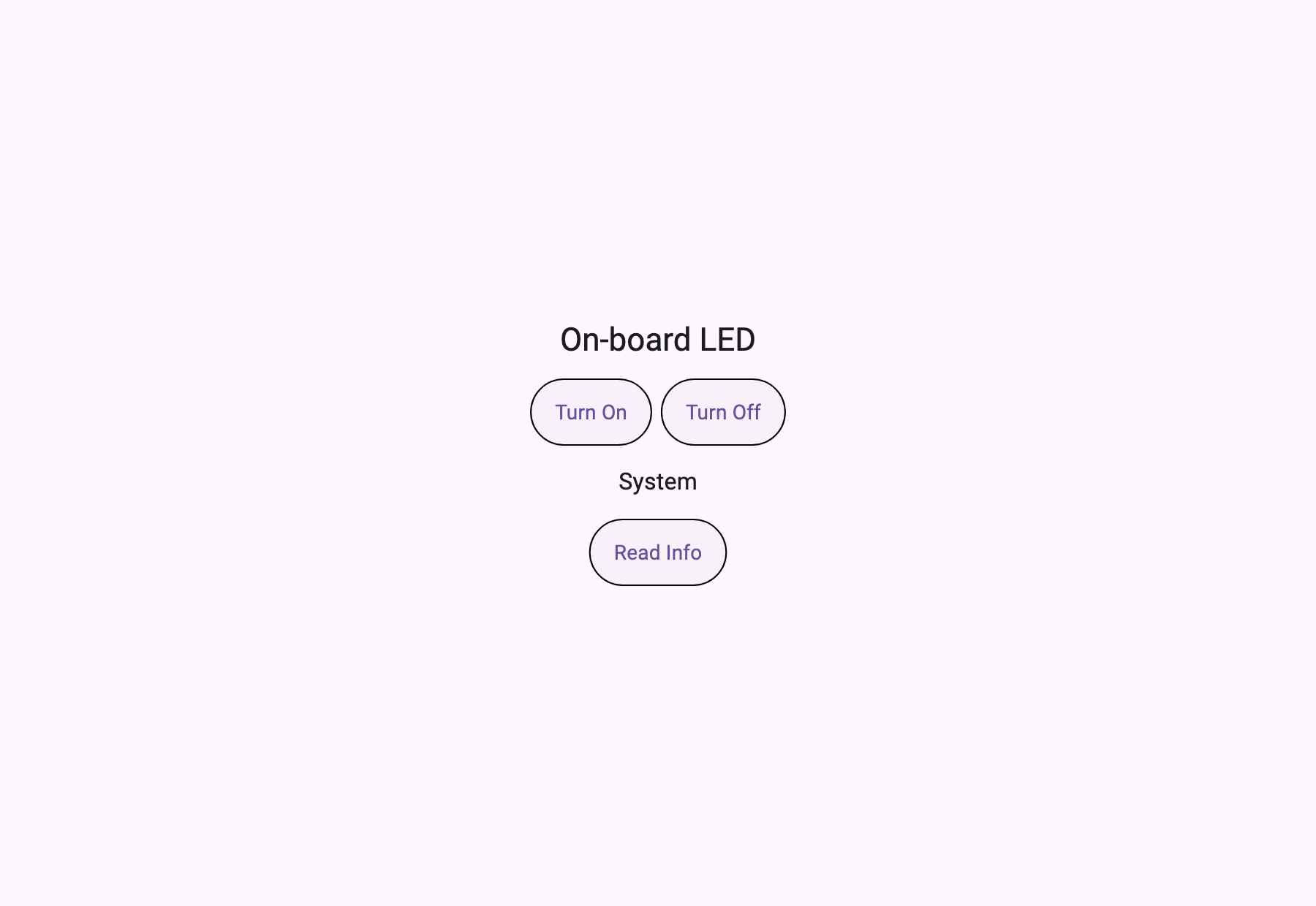
Read ui://app and the screen definition comes out.
[serial] ui://app — 656 B, type "page", title "WeAct H723 MCP Node"656 bytes. That is what one screen costs. The client has not one line of UI code for this board — it receives and draws.
Press it and the board responds
The screen's button calls led.set. A real round trip.
[serial] led.set({"on":true})  -> "LED on"                      (1 ms)
[serial] sys.info({})          -> "LED=on uptime=205491208ms"   (10 ms)
[serial] led.set({"on":false}) -> "LED off"                     (10 ms)
[serial] sys.info({})          -> "LED=off uptime=205491232ms"  (11 ms)
[serial] uptime advanced 205491208 -> 205491232 ms
The LED on the board on the desk went on and off. And look at the last line — uptime advanced from 205491208 to 205491232, 24 milliseconds forward. That is not a canned answer; it is what the board was counting at that moment. A recorded response gives the same number when you ask twice.
Round trips are 1 to 11 milliseconds, because this is over UART.
The same client attaches to a different chip
That is what this structure is worth. The same code attached to an ESP32 across Wi-Fi.
[tcp] connected via tcp_bridge mcp-esp32.local 6270
[tcp] tools: led.set, sys.info
[tcp] ui://app — 158 B, type "application", title "ESP32 MCP Node"
[tcp] application — initialRoute "/" -> ui://page/main
[tcp] ui://page/main — 1894 B
[tcp] led.set({"on":true}) -> "LED on"  (89 ms)
[tcp] uptime advanced 67004328 -> 67004391 ms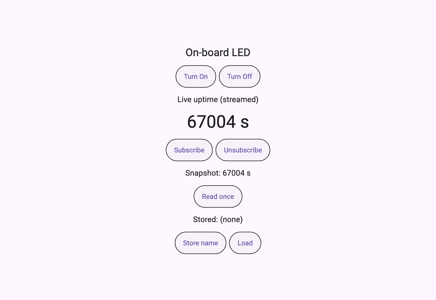
Different vendor's chip, different transport, same client. The one thing that changed is which bridge program runs.
And the two boards' screens are structured differently. The STM32 hands over a single page (type: "page", 656 B); the ESP32 hands over an application with routes (type: "application", 158 B plus a 1894 B page). The board decides the shape of its own screen.
Latency differs. UART is 1–11 ms, Wi-Fi TCP is 17–89 ms. Different orders of magnitude, and that difference divides UI design — at single digits you can expect "press and it's done"; at tens of milliseconds you have to draw a waiting state.
The transport is one program
Here is how the client was kept ignorant of serial: the transport was pulled out into a separate program.
mcp_client  ──stdio──▶  serial_bridge  ──UART──▶  STM32H723
mcp_client  ──stdio──▶  tcp_bridge     ──TCP───▶  ESP32
The bridge passes newline-delimited JSON straight through. The serial side turns off terminal processing with cfmakeraw; the TCP side uses TCP_NODELAY so short requests don't sit in a buffer.
/* Same rule: only JSON lines are the protocol. If the board prints
 * a note onto the same stream, the client must not choke. */
if (up[0] == '{') { printf("%s\n", up); fflush(stdout); }
else              { fprintf(stderr, "[board] %s\n", up); }
Choosing a transport shrank to choosing which program to launch. Not a byte of the client changes.
Along the way the client violated the spec
Attached to a real board, listResources() died instantly.
type 'Null' is not a subtype of type 'String'The board returned a resource with no description, and mcp_client 1.1.1 was casting that field as non-null. The MCP spec makes description optional, and the board was right. It was already fixed in 2.1.0, so upgrading resolved it.
A simulator-only run would never have surfaced this. My own simulator would always have filled description in.
Verification
$ bash verify.sh
   [1/6] bridges (C)
   [2/6] serial board?  /dev/cu.usbmodem365D395E33331 -> WeAct H723 MCP Node
   [3/6] network board? (mDNS _mcp._tcp)  ESP32 MCP Node -> mcp-esp32.local:6270
   [4/6] probe + real render
   [5/6] checks
   2 board(s) · 2 transports · LED round-tripped on both · uptime advanced on both
This sample has no simulator. If the board isn't attached, it says where it looked and fails.
[ -n "$SERIAL" ] || echo " none found on /dev/cu.usbmodem* or /dev/cu.usbserial*"Because hardware verification that passes without hardware is not verification.
What this board sells
The cost of putting a screen on an eval board moved from a graphics stack plus a rebuild to two tools plus 656 bytes of definition.
Why does that matter to a chip company? You don't reburn certified firmware to add a screen. You don't reissue firmware when a customer wants the screen changed. The screen is drawn outside, and the board only says what it can do.
Irrigation controller or greenhouse gateway — whatever attaches, the board says the same thing.
Run it yourself
cd serial_bridge && cc -O2 -o serial_bridge serial_bridge.c && cd ..
cd tcp_bridge    && cc -O2 -o tcp_bridge    tcp_bridge.c    && cd ..

bash verify.sh          # find board → connect → tools/resources → open it in AppPlayer
What to take
- Two bridges —
serial_bridge.candtcp_bridge.c. Compile as-is and they attach to any client - The board's minimum answers —
initialize,tools/list,resources/read; three of them and a screen appears - A hardware verification script — a
verify.shthat will not pass without a board
To use your own board — change only the tool names and the ui://app JSON in your firmware. Don't touch the bridge or the client. Different transport, different bridge.
Practice task
Add a second device to the example. List every file you changed. The host should not be one of them.